CAD and BIM are both used in structural steel projects, but they serve fundamentally different purposes. We break down the key differences, when to use each approach, and what the choice means for your project.
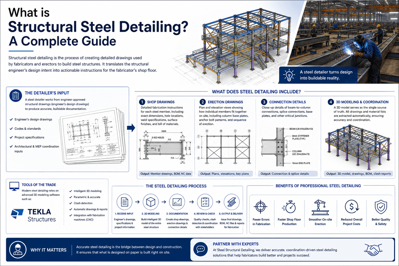
The construction industry has undergone a significant digital transformation over the past two decades, and two technologies sit at the heart of that shift: CAD (Computer-Aided Design) and BIM (Building Information Modeling). While both are used in structural steel projects, they serve fundamentally different purposes — and understanding the distinction helps project teams make better decisions about their detailing approach.
This article explains what each technology does, how they differ in practice, and when each is the right choice for a structural steel project.
## CAD: The Traditional Approach
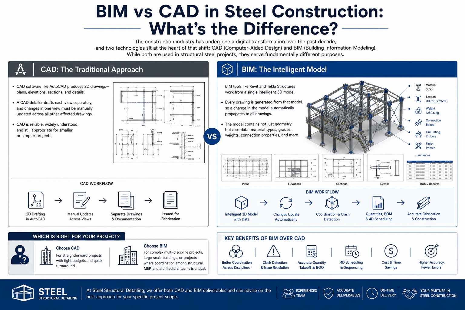
CAD software — with AutoCAD being the most widely used tool — produces 2D drawings. Plans, elevations, sections, connection details, and schedules are each drafted as separate drawing files. A CAD detailer constructs each view independently, using standard linework, hatching, dimensions, and text annotations to convey the required information.
The strength of CAD is its simplicity and universality. AutoCAD is well understood across the construction industry. DWG files are universally compatible. For experienced detailers, CAD production can be fast on smaller or repetitive projects. For simpler steel structures — a straightforward warehouse, a single-story industrial building with a standard portal frame — CAD detailing is often perfectly adequate and frequently more cost-effective than BIM.
The limitation of CAD is that there is no underlying model connecting the drawings. If a beam depth changes, a CAD detailer must manually update every affected view — the plan, the elevation, the section, the connection detail, and the material list — separately. This is both time-consuming and error-prone. Inconsistencies between drawing views are one of the most common sources of RFIs and field conflicts on projects detailed in 2D CAD.
CAD also provides no inherent capability for clash detection. If a structural beam conflicts with a mechanical duct, that conflict won't be found through the CAD workflow — it will be discovered when the trades arrive on site at the same location.
## BIM: The Intelligent Model
BIM tools — principally Tekla Structures for structural steel detailing and Autodesk Revit for multi-discipline coordination — work from a single intelligent 3D model. Every structural element is modeled as a parametric object with associated data: section size, material grade, length, orientation, connection type, surface treatment, weight.
All drawings are generated automatically from the model. A shop drawing for a specific beam is extracted from the model geometry. An erection drawing is a view of the full model. A material list is a model-generated report. The consequence is absolute dimensional consistency across the entire drawing set — because every number comes from the same source.
When a design change occurs, the detailer updates the model. All affected drawings regenerate automatically, and the model can be checked to identify any new conflicts the change may have created. This dramatically reduces the revision cycle time compared to CAD, particularly on complex projects with frequent design changes.
## Clash Detection: BIM's Most Tangible Value
One of the most immediately valuable capabilities of BIM is clash detection. On a construction project, structural steel must coexist with architectural elements, mechanical systems, electrical systems, and plumbing. In a 2D CAD workflow, coordination between these disciplines is done manually — overlaying drawing sets and visually checking for conflicts. This process misses a substantial proportion of actual clashes.
In a BIM workflow, models from all disciplines are federated in a platform such as Autodesk Navisworks. The software runs automated clash checks — finding every location where structural steel intersects with a duct, a pipe, a conduit, or an architectural element. These clashes are catalogued with precise locations and severity levels, assigned to responsible disciplines, and tracked to resolution before construction begins.
The cost savings from clash detection are well documented. A clash found in the model before construction costs almost nothing to resolve — the detailer adjusts the model, new drawings are extracted, and the problem is eliminated. The same clash found on site after steel has been erected can require field modification of fabricated steel, rerouting of installed systems, and significant contractor time and coordination cost.
## LOD: Level of Development in BIM
BIM projects are typically defined by a target Level of Development (LOD), which describes how much information and geometric precision a model element carries at each project stage. LOD 100 is a massing model suitable for early feasibility. LOD 200 adds approximate geometry for schematic coordination. LOD 300 reaches construction document precision — accurately dimensioned elements with full specification data, suitable for clash detection and design coordination. LOD 350 adds interface geometry showing how elements connect to other systems. LOD 400 is fabrication-level detail, equivalent to the information in a shop drawing. LOD 500 is the verified as-built condition.
Understanding LOD matters because modeling to a higher LOD than necessary for the project purpose wastes time and budget. A project using BIM for early coordination doesn't need LOD 400 models. A project using BIM to drive fabrication does. Establishing the target LOD at project kickoff — for each discipline and each model use case — is a fundamental BIM management task.
## 4D BIM: Construction Scheduling
Beyond geometry and clash detection, BIM enables 4D scheduling — linking model elements to a construction program to create a time-based simulation of the build sequence. In a 4D model, you can watch the steel frame rise floor by floor, see when each crane pick happens, and identify sequence conflicts before construction begins.
For complex projects — high-rise buildings, large industrial facilities, phased construction in occupied buildings — 4D BIM is a powerful communication and planning tool. It makes the construction program tangible for project stakeholders who aren't fluent in Gantt charts and gives the site management team a visual reference for planning logistics.
## Which Approach is Right for Your Project?
The choice between CAD and BIM isn't binary — it's a judgment based on project complexity, multi-discipline coordination requirements, budget, and program.
For straightforward single-story structures, simple portal frame buildings, or projects with tight budgets and fast turnarounds, CAD detailing is often the most practical choice. Experienced CAD detailers working on familiar project types are fast and cost-effective.
For complex multi-story buildings, projects with significant MEP coordination requirements, projects being managed under a BIM Execution Plan, or projects where the model data will be used for quantity extraction, 4D scheduling, or facility management — BIM delivers clear value that justifies the additional upfront investment.
Many projects use both: BIM for coordination and the overall model, CAD for specific details or for producing drawings in a format required by a particular fabricator or jurisdiction. The right answer depends on the specific project, not on a general preference for one technology over another.
At Axiom Steel Detailing, we work in both environments and can advise on the most appropriate approach for your project based on its scope, schedule, and coordination requirements.