Understanding rebar detailing helps contractors communicate better with detailers, avoid costly errors, and keep concrete projects on schedule. This guide covers everything from bar bending schedules to code compliance.
Rebar detailing is the process of preparing placement drawings and bar bending schedules (BBS) for reinforcing steel in concrete structures. It translates the structural engineer's reinforcement design into practical, site-ready and fabrication-ready documentation that rebar benders, placing crews, and concrete contractors can follow without ambiguity.
For contractors, a working understanding of rebar detailing — what a good set of documents looks like, what common errors occur, and how to work effectively with a detailer — can prevent costly field problems and keep concrete pours on schedule.
## What a Rebar Detailing Package Contains
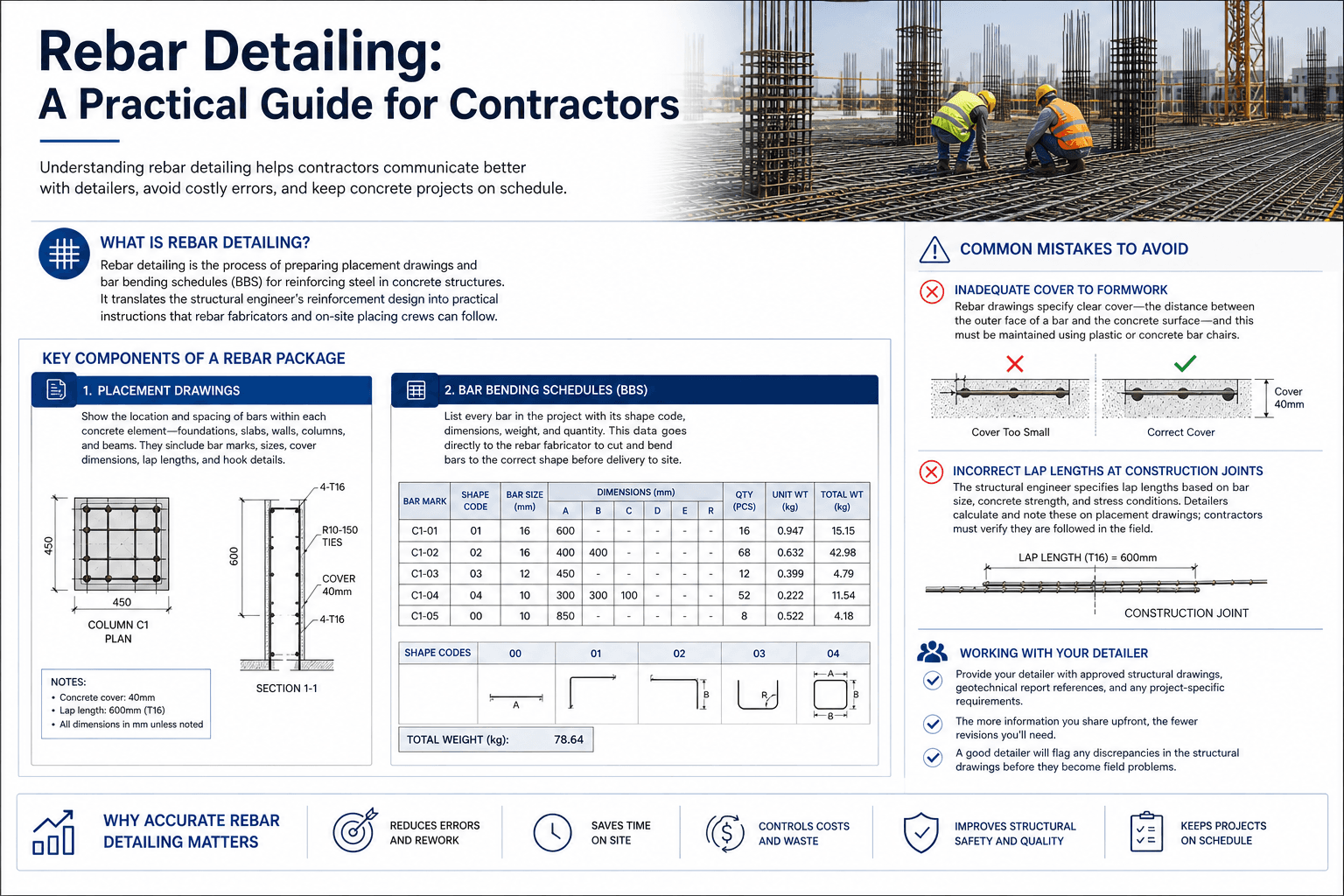
A complete rebar detailing package for a structural concrete project typically includes three main document types.
Placement Drawings show the location, size, spacing, and arrangement of every reinforcing bar within each concrete element. For foundations, this means plan views of pad footings, strip footings, pile caps, and raft slabs showing bar arrangements, spacings, and cover. For superstructure elements — columns, beams, slabs, walls — placement drawings show the bar layout at every level, including how bars change between floors. Good placement drawings include construction joint locations, lap splice positions, additional reinforcement at openings and re-entrant corners, and chair and spacer specifications.
Bar Bending Schedules (BBS) list every reinforcing bar in the project with its unique bar mark, diameter, shape code, cutting length, bending dimensions, and total quantity. The BBS is essentially an order sheet for the rebar fabricator — they use it to cut and bend every bar to the specified shape before delivery to site. It also serves as a procurement document, since the total weight per bar diameter and per element type is calculated in the BBS.
The relationship between placement drawings and the BBS must be exactly consistent. Every bar mark that appears on a placement drawing must have a corresponding entry in the BBS, and vice versa. Mismatches between these two documents are a common source of field confusion and ordering errors.
Foundation and Special Element Details are often separate from the main placement drawings. Complex elements such as deep pile caps with multiple layers of heavily congested reinforcement, retaining walls with counterforts, transfer beams with high-density reinforcement, or post-tensioned elements typically require detailed sections and close-up views that can't be clearly shown at the standard scale of placement plans.
## Bar Bending Schedules in Detail
The bar bending schedule deserves particular attention because it's the document that controls what gets fabricated and delivered to site. An error in the BBS — a wrong dimension, a wrong shape code, a miscalculated cutting length — results in bars arriving on site that don't fit. Correcting this after the fact means either returning bars for refabrication (which takes time) or cutting and bending on site (which is less precise and more labor-intensive).
Shape codes in the BBS follow standard references. In the United Kingdom, BS 8666 defines standard bar shapes and their associated dimension letters. In Australia, AS 1085 and the associated CCAA guidelines define shape codes. In the United States, CRSI (Concrete Reinforcing Steel Institute) publishes standard bend configurations. The shape code communicates the form of the bar — straight, with one hook, with two hooks, a U-bar, an L-bar, a stirrup shape — through a compact code that both detailers and rebar fabricators understand without ambiguity.
Cutting lengths are calculated by the detailer from the placement dimensions and the applicable bending deductions. Bending deductions account for the fact that bending elongates the bar along the outer radius — a correctly bent bar is shorter in total straight material than a naive calculation would suggest. The required mandrel diameter for each bend affects the deduction, and this varies by bar diameter and code.
## Cover: The Most Common Source of On-Site Problems
Concrete cover — the distance between the surface of a reinforcing bar and the nearest face of the concrete — is specified by the structural engineer based on durability requirements, fire resistance, and exposure conditions. It's one of the most frequently violated requirements on construction sites, and the consequences of inadequate cover are long-term: accelerated corrosion of the reinforcement, concrete spalling, and structural capacity degradation.
Placement drawings specify clear cover (the gap between the outer face of the bar and the concrete surface) for every element and face. Bar chairs and spacers are specified to maintain this cover during concrete placement. Contractors must ensure that the correct spacers are in place and that they're positioned at the required spacing to prevent bars from deflecting during poring.
Inspectors checking reinforcement before pours should verify cover systematically. The most common problem areas are the underside of slabs (where bar chairs may have been disturbed during placing of the top mat), column cage sides (where spacers may be missing or at wrong heights), and wall elements (where bars can be pushed against the form by workers walking on the cage).
## Lap Lengths and Splice Locations
Reinforcing bars come in standard mill lengths — typically 12 meters in metric markets. In any concrete element longer than a mill bar, bars must be spliced. The structural engineer determines where splices are permitted and how long they must be. Detailers show splice locations and calculate lap lengths on the placement drawings.
Lap lengths are calculated from the applicable code — ACI 318 in the United States, BS EN 1992 in the UK, AS 3600 in Australia — using bar diameter, concrete compressive strength, bar stress level, and splice classification. Tension laps are generally longer than compression laps. Class B laps (where more than 50% of bars are spliced at a section) are longer than Class A laps.
Contractors must respect splice zone locations. Splices placed in high-moment zones that weren't designed for them can compromise structural capacity. If a contractor needs to adjust splice locations for construction reasons, this requires structural engineer review and approval — it's not a field decision.
## Seismic Detailing Requirements
In seismic zones, rebar detailing is subject to additional requirements that don't apply in low-seismic areas. In the United States, ACI 318 Chapter 18 specifies special seismic detailing provisions for concrete frames, walls, and diaphragms. These include requirements for confinement reinforcement, closely spaced hoops and spirals in column and beam plastic hinge zones, cross-tie configurations, and specific lap splice restrictions in high-ductility zones.
Seismic rebar details are more congested and more complex than standard detailing. Contractors working on seismic projects need to allocate more time for placing reinforcement in the special moment frame or special shear wall elements, where placing crews need to thread bars through dense hoop and crosstie configurations. Communicating this complexity to site supervisors before work begins prevents schedule surprises.
## Working Effectively with Your Rebar Detailer
The quality of the output from a rebar detailer is substantially affected by the quality of the input you provide. The more complete and clear your project information, the less time is spent on clarifications and revisions.
Provide approved structural drawings — not preliminary or unapproved issue versions. Structural engineers sometimes issue drawings for detailing ahead of final approval; while this can save time, it creates risk if changes occur after detailing has begun. Establish a clear protocol for how design changes are communicated during the detailing process.
Provide the structural specification, including concrete mix grades for each element type, cover requirements per exposure class, and any project-specific reinforcement product requirements. If the project uses headed studs, mechanical couplers, or fiber reinforcement in addition to conventional rebar, this needs to be known upfront.
Flag any unusual conditions: construction joints in structurally sensitive locations, phased pours where bars must be prepared in advance, elements with tight congestion or restricted access for concrete placement. A good detailer will identify constructability issues and raise them formally before they become site problems — but the more context you provide, the better equipped they are to do so.