Structural steel detailing is the process of creating detailed drawings used by fabricators and erectors to build steel structures. Learn what it involves, why it matters, and how modern software has transformed the discipline.
Structural steel detailing is a specialized discipline within structural engineering and construction. It involves producing comprehensive shop drawings, erection drawings, and 3D models that guide the fabrication and assembly of steel structures. These documents translate the structural engineer's design intent into actionable instructions for the fabricator's shop floor and the erection crew on site.
Understanding what structural steel detailing actually encompasses — and why getting it right matters so much — is valuable for anyone working in steel construction, whether you're a fabricator, a structural engineer, a general contractor, or a project owner.
## What Does a Steel Detailer Actually Do?
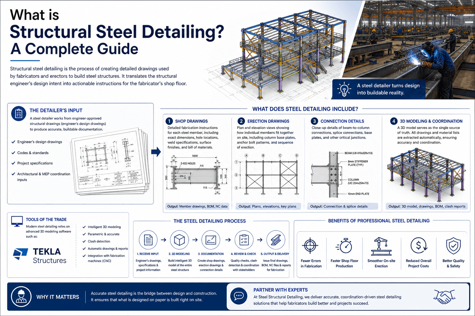
A steel detailer works from engineer-approved structural drawings (commonly called engineering drawings or design drawings) to produce a complete fabrication and erection package. The structural engineer tells you what the steel needs to do — carry loads, resist lateral forces, span certain distances. The detailer translates that into the precise, dimensioned instructions that make fabrication and assembly possible.
The output of a detailing engagement typically includes several document types, each serving a different purpose in the construction workflow.
Shop Drawings are the core deliverable. These are detailed fabrication instructions for each individual steel member — beams, columns, braces, plates, and every other component. A shop drawing for a single beam shows its exact length, the location and diameter of every hole, the weld size and type at each connection point, the surface treatment specification, the member piece mark, and a bill of materials listing every component that makes up the assembly. Shop drawings are what the fabricator's shop floor workers use to cut, drill, punch, and weld each piece. Errors here have direct consequences: a mislocated hole means a member won't bolt up on site, and the cost of rework — especially after a piece has been painted and shipped — is significant.
Erection Drawings show how all the individual pieces fit together on site. These are plan views and elevations that show where each column, beam, brace, and connection lands in the overall structure. Erection drawings include column base plate locations, anchor bolt patterns, erection phases or sequences, temporary bracing requirements, and piece mark schedules that tie back to the shop drawings. The raising gang uses erection drawings as their roadmap — without them, a pile of uniquely-marked steel pieces would be nearly impossible to assemble correctly and safely.
Connection Detail Drawings are close-up details of the junctions where members meet. Beam-to-column connections, column splices, base plates, gusset plate connections at braced frames, moment connections at moment frames — each of these requires its own detailed drawing that shows bolt quantities and grades, weld sizes and types, plate dimensions, and clearance information. Connection details are often the most technically complex drawings in a steel package, because this is where the structural behavior of the frame is realized in physical geometry.
Anchor Bolt Plans are produced for the concrete contractor before any steel arrives on site. These drawings show exactly where foundation anchor bolts must be set, including their spacing, projection above the concrete, thread engagement length, and orientation relative to column centerlines. If anchor bolts are set incorrectly, columns won't align with the structural grid — a problem that can be extremely expensive to resolve after concrete has cured.
## The Role of 3D Modeling Software
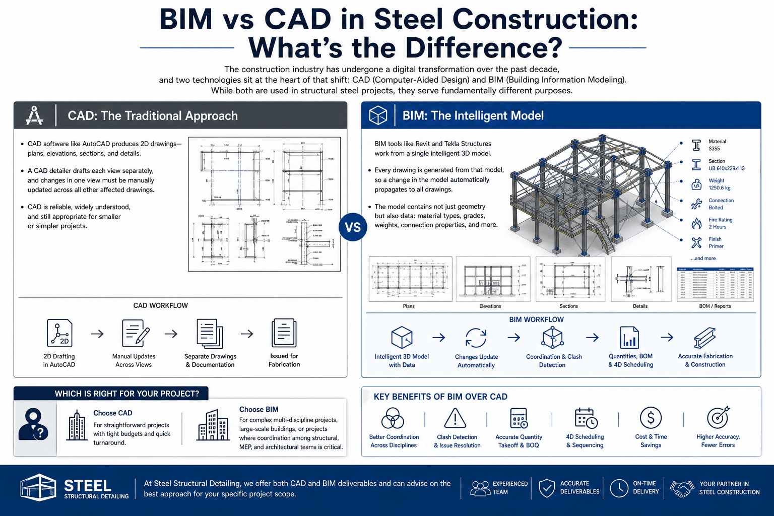
Modern structural steel detailing relies heavily on 3D modeling platforms, with Tekla Structures being the industry standard for complex and high-value projects. Rather than drafting each drawing view independently in 2D CAD, a Tekla detailer builds a complete virtual replica of the steel structure in three dimensions. Every member is modeled with its correct section size, length, orientation, and material grade. Every connection is modeled explicitly — bolt groups, welds, plates, stiffeners.
Once the 3D model is complete and reviewed, all drawings are extracted automatically from the model. This means shop drawings, erection drawings, connection details, and material lists all come from the same geometric source. The consequence is that dimensional consistency is guaranteed across the entire drawing set — the same beam length that appears on the shop drawing also appears on the erection drawing, because both are generated from identical model geometry.
This approach also enables clash detection. The Tekla model can be checked against architectural and MEP (mechanical, electrical, plumbing) models to identify conflicts before construction begins — a duct that would run through a beam web, a pipe that conflicts with a column, a facade anchor that conflicts with a structural connection. Catching these issues in the model costs almost nothing. Finding them on site is expensive.
## AISC Standards and Code Compliance
In the United States, structural steel detailing follows standards published by the American Institute of Steel Construction (AISC). The AISC Code of Standard Practice defines the responsibilities of fabricators, detailers, and engineers in the steel construction process. AISC 360 governs the design of structural steel for buildings, while AISC 341 covers seismic provisions for steel structures in high-seismic zones.
Weld specifications on shop drawings follow AWS D1.1, the Structural Welding Code published by the American Welding Society. Bolt specifications reference AISC and RCSC (Research Council on Structural Connections) standards. A properly prepared shop drawing set references all applicable standards explicitly, giving fabricators, welding inspectors, and special inspectors a clear compliance baseline.
For projects in the UK, detailing follows BS 5950 or the Eurocodes (BS EN 1993). Australian projects reference AS 4100. Detailing firms working across multiple markets need to understand not just the geometric requirements of these codes but the drawing conventions they prescribe — because a drawing that's perfectly correct under AISC conventions may be difficult for a UK fabricator to interpret if it doesn't follow British drawing practice.
## Why Accurate Detailing Matters
The connection between drawing quality and project outcomes is direct. Fabrication shops that receive complete, accurate, clearly formatted shop drawings run efficiently — machines are programmed correctly the first time, assemblies are welded in the right sequence, and pieces move through the shop without delays. Erection crews that have clear, complete erection drawings work safely and quickly.
Conversely, incomplete or inaccurate drawings generate RFIs (Requests for Information) that slow fabrication, create rework after fabrication, and cause delays and conflicts on site. The cost of resolving a detail error after steel has been fabricated, painted, and shipped is many times the cost of getting it right in the drawing.
For fabricators and contractors evaluating detailing service providers, the key indicators of quality are thoroughness of the checking process, clarity of the RFI procedure, turnaround time reliability, and the detailer's understanding of practical fabrication and erection requirements — not just the ability to produce technically correct geometry.
Professional steel detailing is not a commodity. The difference between a drawing package that works and one that doesn't shows up in every phase of the project that follows.